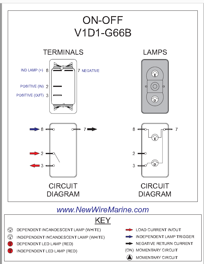
Boat Rocker Switch Wiring Diagram
Pin 3 is where the switch is either connected to ground or left open.
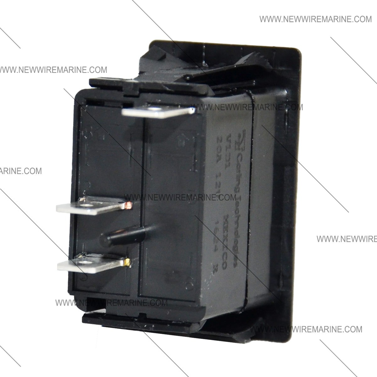
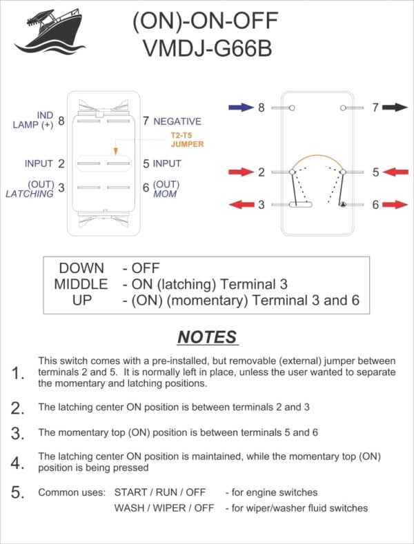
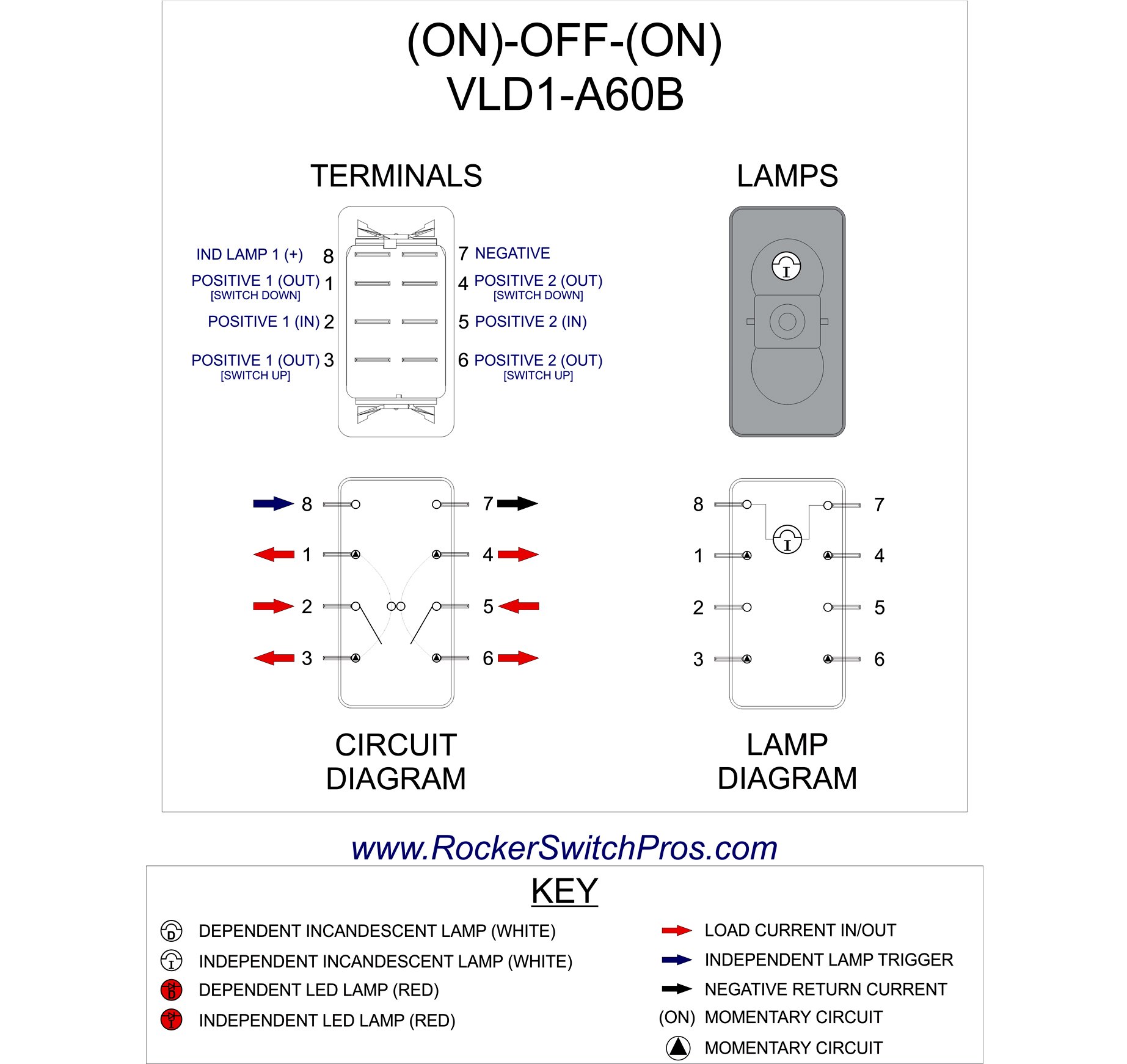
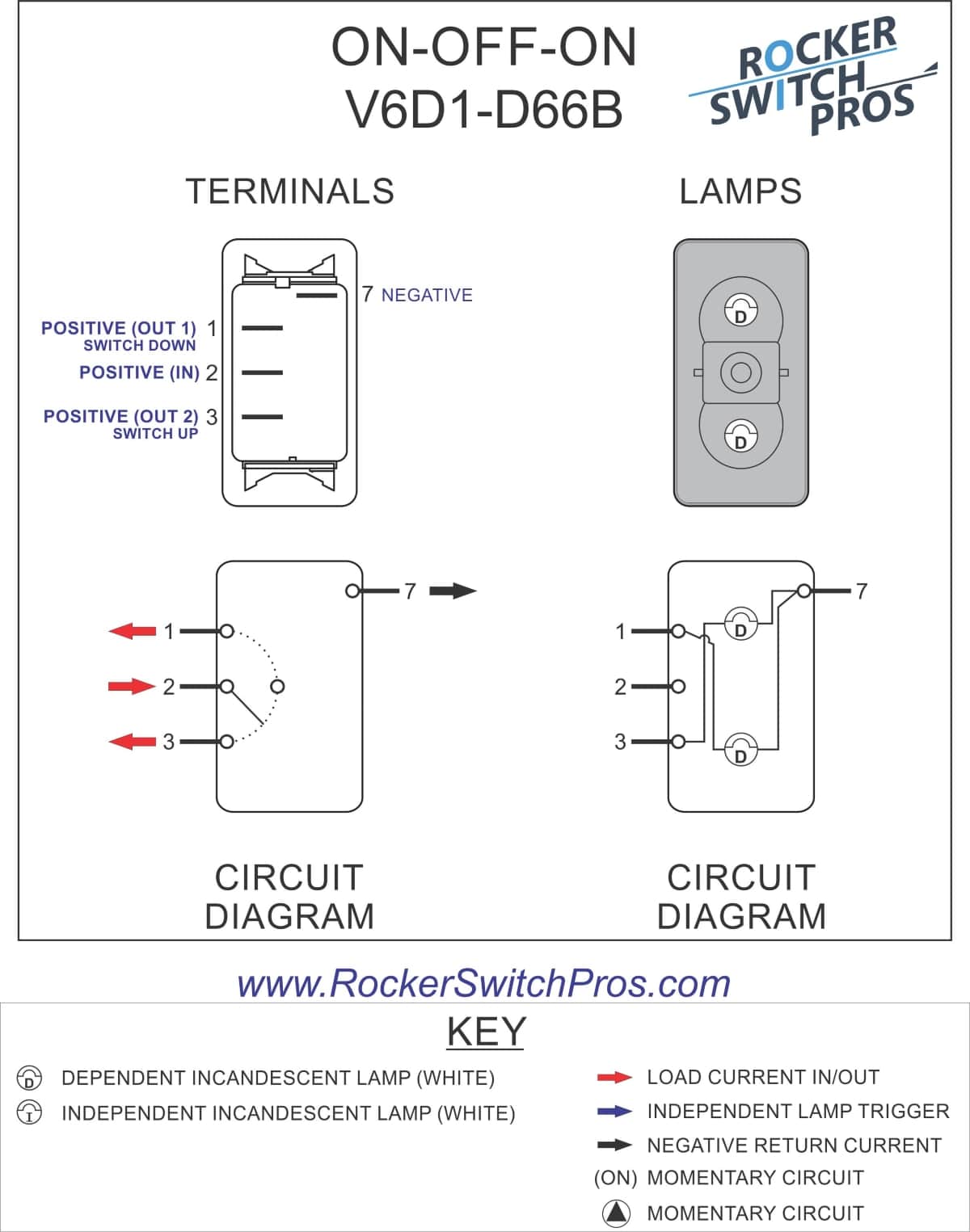
Boat rocker switch wiring diagram. The section below has wiring diagrams the are specific to marine rocker switch panels. This rocker switch body is meant to be paired a etched or printed rocker switch cover for a complete switch unit. Id rather have a dead battery than a swamped boat. With just a few small jumpers our switch selection can be used for a multitude of different functions.
This switch will light the bottom light when it is down and the upper light when it is up. Its pretty standard in boat wiring to bypass the main battery switch for one thing. The diagram below represents the schematic diagram for a spst rocker switch. This is a rocker switch body only.
Each of our carling rocker switch bodies have the generic wiring diagram loaded into that products own page see photo right. We have wiring diagrams and wiring guides on how to wire a 10 terminal navancher on off on 3 way carling contura rocker switch as well as a wiring diagrams in how to wire a 10 terminal bilge auto manual on off on 3 way carling contura rocker switch for. This way even if your battery switch is off if your boat starts filling with water the pump will still kick on. Pin 1 is where the rocker switch receives the input power.
Super easy boat wiring and electrical diagrams. I have 2 other wiring videos with different set ups to give you more ideas for how to rig your boat effectively and safely and accomplish what you need for boat wiring and electrical work switch. 2 usb ports are sufficient to meet charge demand. Pin 2 is where the accessory that the switch is going to turn on is connected.
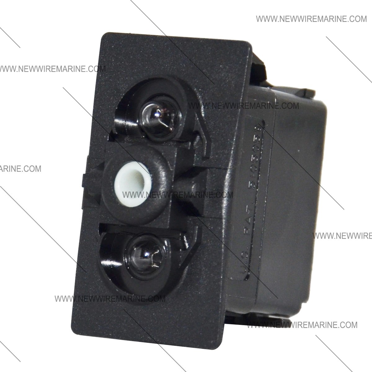
In this extremely common configuration a single switch is. Boat switch panel with marine grade rocker switches and rubber seal cap to keep it water tight. All actuators sold on this site will fit this switch.


