Body Builder Wiring Diagram Ford F 450

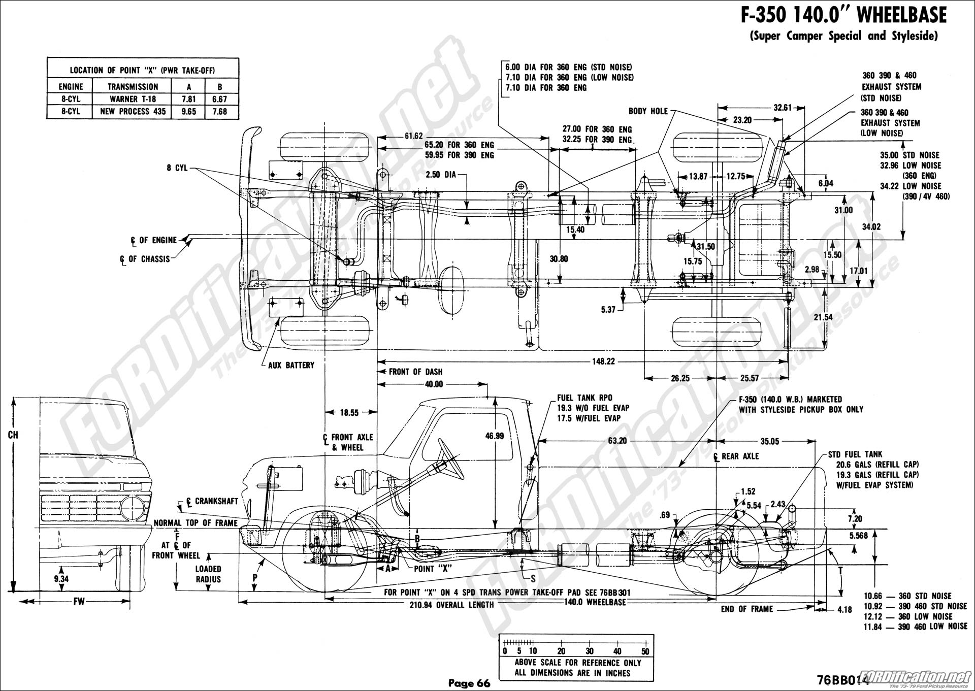
General body material and construction measurements 66 air conditioning charging chart 67.
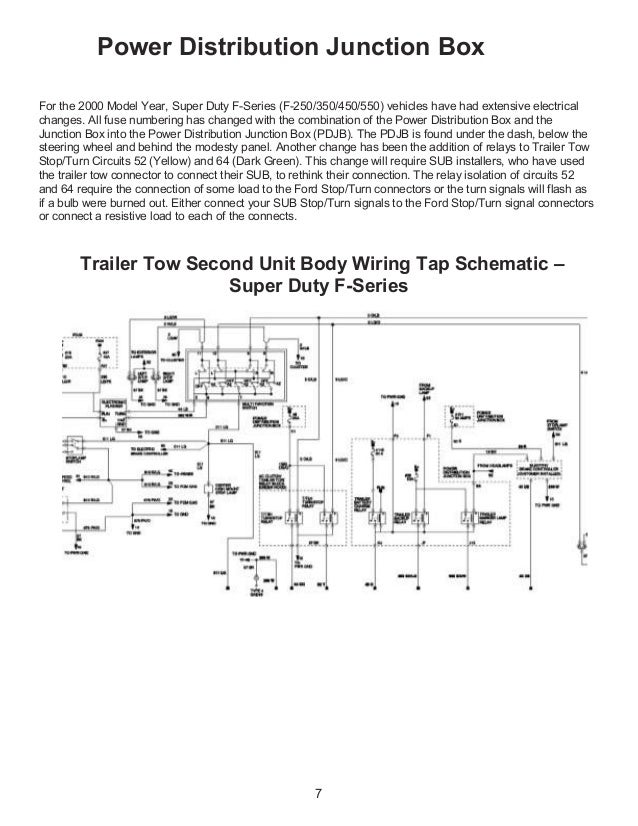
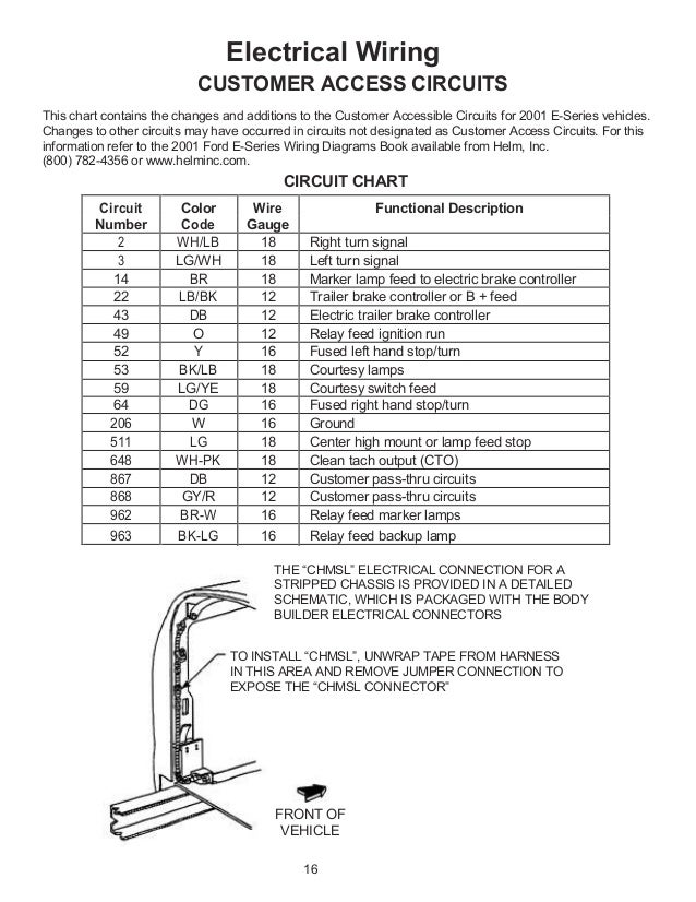
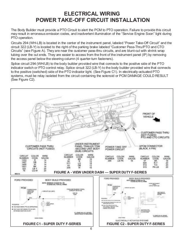
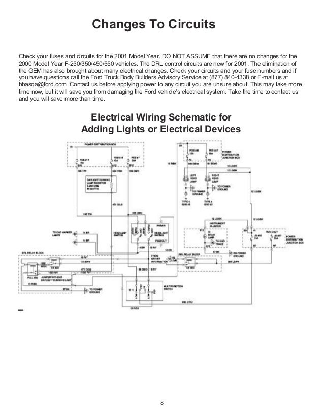
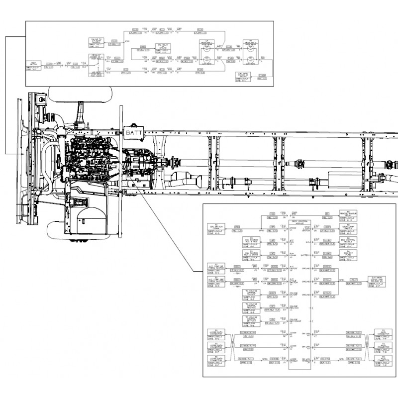
Body builder wiring diagram ford f 450. Ford f 450 repair manual online. Ford f 450 trailer wiring diagrams light wiring diagram ford f450 trailer wiring diagram by bismillah. 1 96 f 550 circuit board assembly ver. However it does not have as sophisticated and electric consuming attributes that rv and other costly trailers may have.
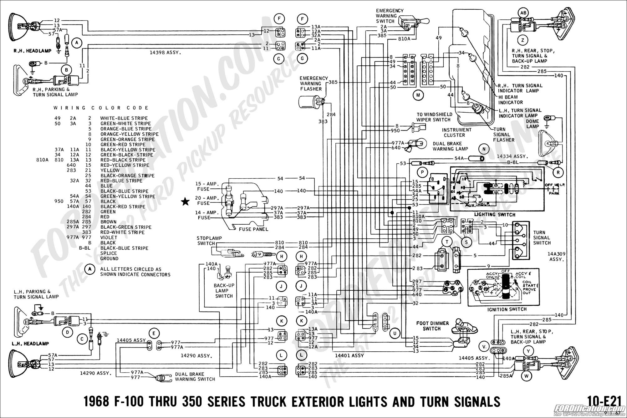
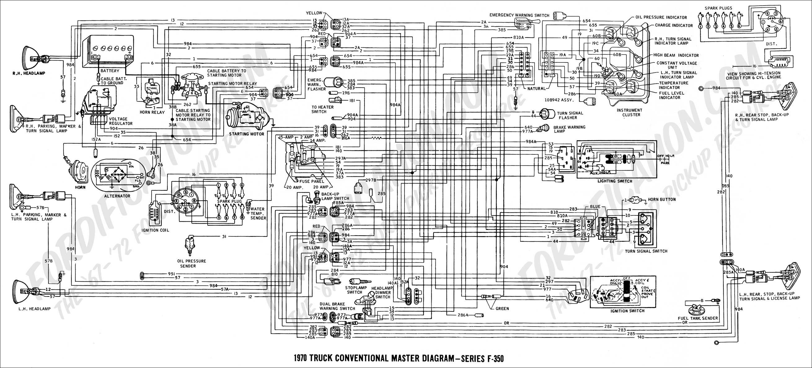
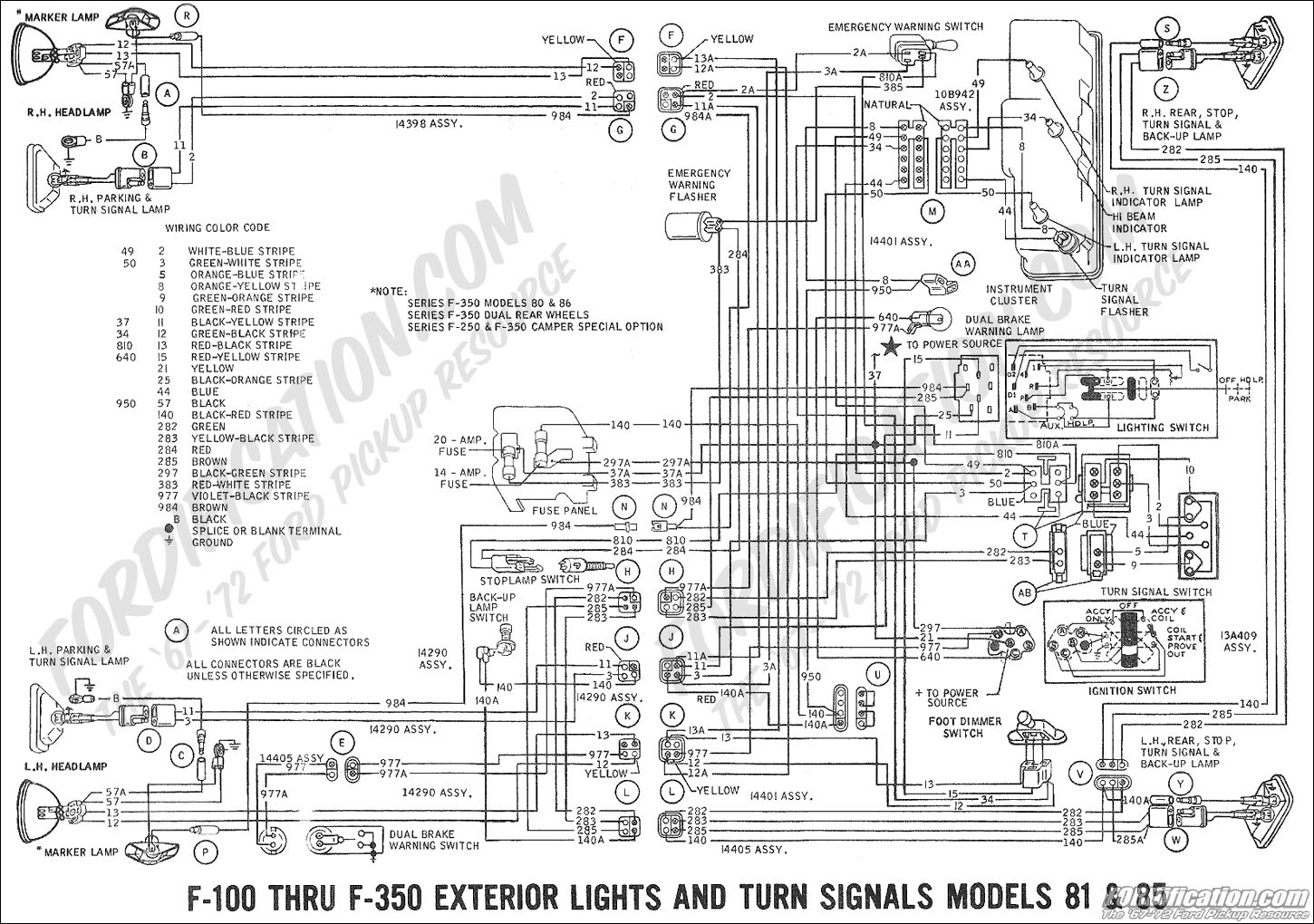
The following information is reproduced directly from the 1970 ford body builders layout book vol. Drivers side wiring diagram 93 e 450 shuttle bus passenger side rear wiring diagram 94 f 550 circuit board assembly ver. Eligibility and required documents. For the driver and one front seat passenger 150 lb.
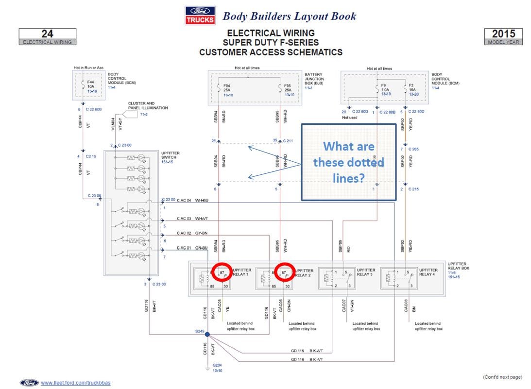
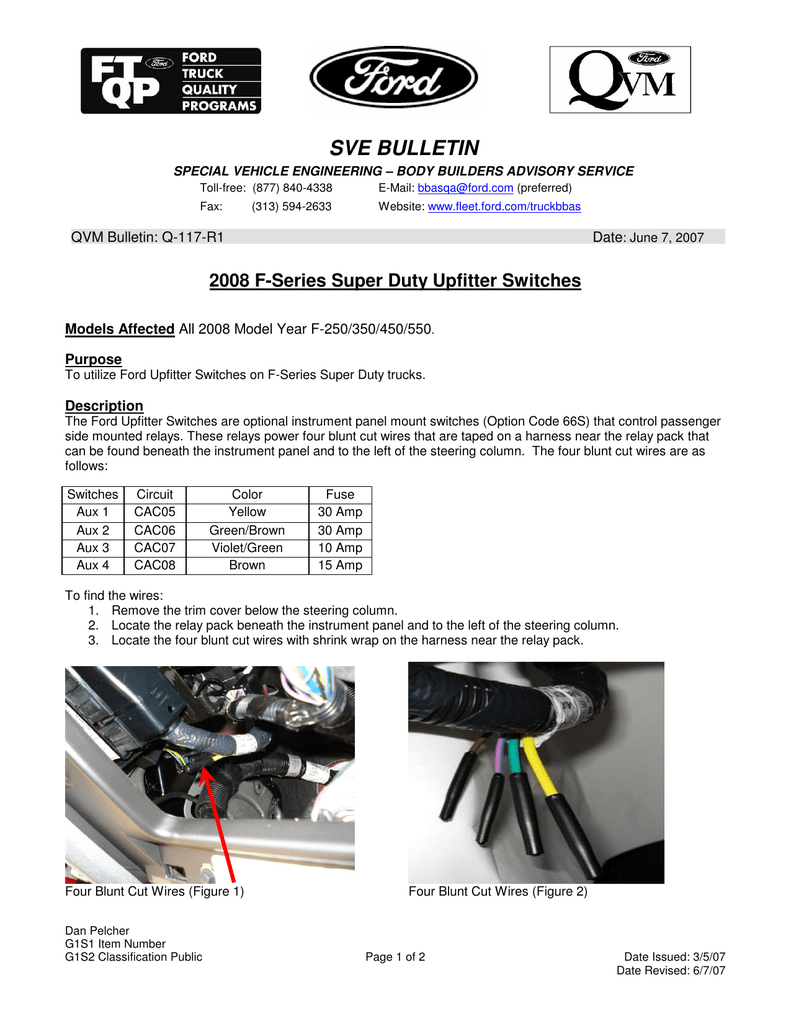
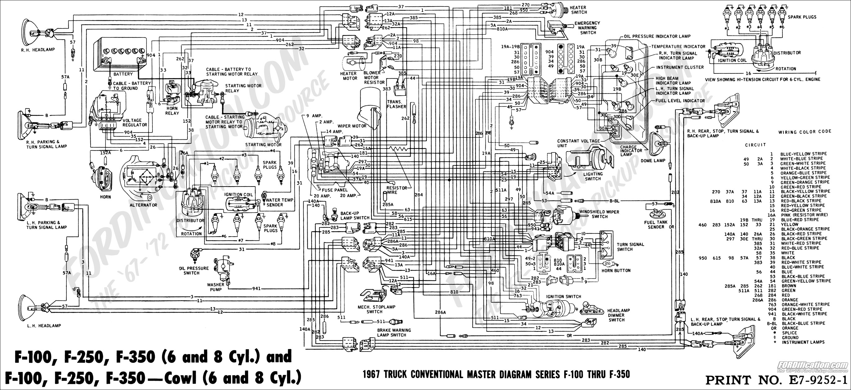
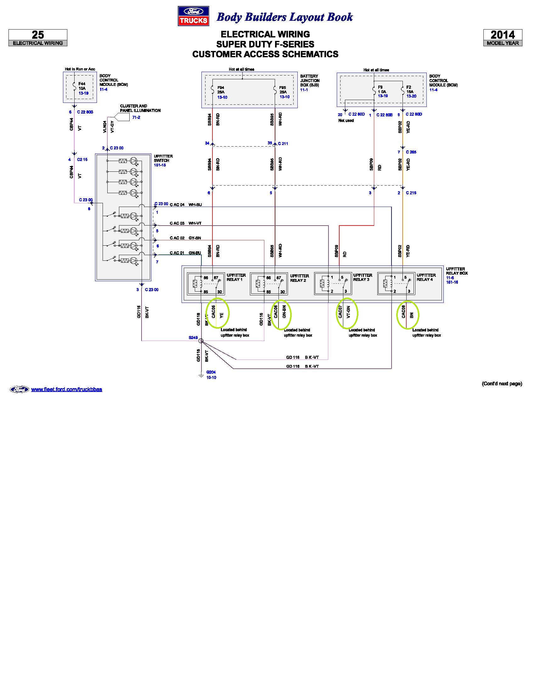
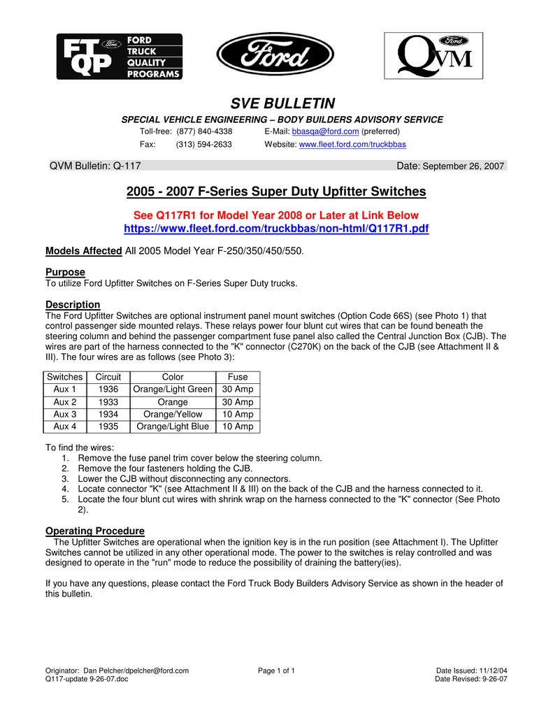
1967 f 100 thru f 350 ignition charging starting and gauges. Description the ford upfitter switches are optional instrument panel mount switches option code 66s that control passenger side mounted relays. Create a fleet user id and password. F 650f 750 smooth refined and powerful the ford class 6 7 trucks offer both diesel and gasoline engines for reliable cost effective performance.
Ford chassis 450550 series. F 450f 550 rc 60ca with 422 aft axle frame extension. Chiltons ford f 450 online manuals provide information for your cars diagnostics do it yourself repairs and general maintenance. 2018 f 350 super duty chassis cab 2018 f 450 f 550 super duty chassis cab percent of body and payload weight on front axle by wheelbasea2c grouped by ca 1 see current body builders layout book for exact dimensions.
Chiltons ford f 450 repair manuals include diagrams photos and instructions you need to assist you in do it yourself f 450 repairs. Purpose to utilize ford upfitter switches on f series super duty trucks. The information is applicable to all 67 72 trucks. 1967 master wiring diagram.
Create a new fin code. 2011 f series super duty upfitter switches models affected all 2011 and later model year f 250350450550. Ford f 450 repair manuals are available at the click of a mouse. Technical drawings and schematics section h wiring diagrams.
