Schematic Ceiling Fan Speed Control Switch Wiring Diagram

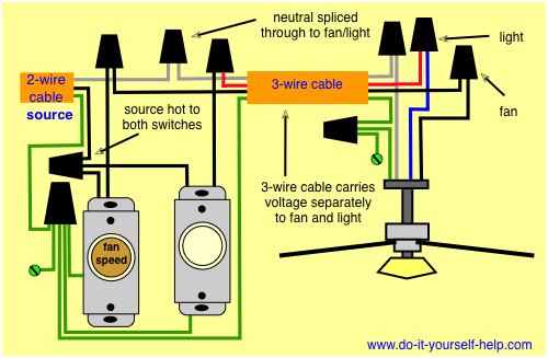
From there two wires run to the ceiling fan.
Schematic ceiling fan speed control switch wiring diagram. The hot source is connected directly to the bottom terminal on the switch. Hunter ceiling fan capacitor wiring diagram http for hampton bay 6. Hunter ceiling fan wiring schematic collections of ceiling fans hunter ceiling fan wiring schematic hunter fan wiring. Ceiling fan capacitor connection diagram how to control speed of fan using speed control switch how to control speed and wire dimmer switch for ceiling fan so we use capacitor with fan but when capacitor become week our fan rpm or speed become slow or if the capacitor stop his duty totally or blown then our fan stop running.
It shows the components of the circuit as simplified shapes as well as the power and also signal connections in between the gadgets. It shows the components of the circuit as simplified forms as well as the power as well as signal links in between the devices. Whether it be a hampton bay hunter or another brand of ceiling fan many fans have the same setup in terms of installation. There are several ways to control ceiling fans and light kits.
From the switches 3 wire cable runs to the ceiling outlet box. Ceiling fan and light kit control options. Assortment of ceiling fan wiring diagram 3 speed. A wiring diagram is a streamlined standard pictorial representation of an electric circuit.
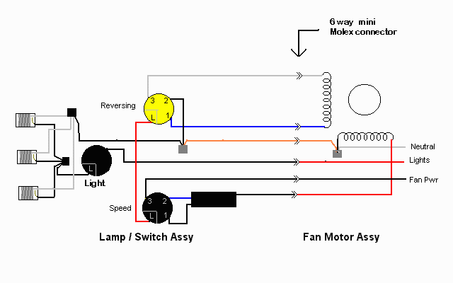
The source is at the switches and the input of each is spliced to the black source wire with a wire nut. In the above ceiling fan speed control wiring diagram i shown the main winding running winding and i connect run wire of motor to the speed control switch and you can see it in above diagram that connection of run wire of motor in switch l point and and 1 and 2 for capacitor. A question we often get asked is where can i find a wiring schematic or wiring diagram for my ceiling fan. Hunter ceiling fan wiring diagram with remote control image.
Wiring diagram for ceiling fan switch new hunter ceiling fan speed. One wireswitch to turn power onoff to the fan and lights at the same time two wireswitches one switch turns power onoff to the fan the other to the lights pull chains to adjust fan speed and lights remote control available on new or existing fans to adjust fan speed and lights. With the below wiring diagrams you can install 90 of ceiling fans no matter the make or model. Ceiling fan wiring diagram with single switch.
This wiring method is used when the power source is from the switch and one wants to control the fan and light from that single switch. This wiring diagram illustrates the connections for a ceiling fan and light with two switches a speed controller for the fan and a dimmer for the lights. It reveals the parts of the circuit as streamlined forms as well as the power as well as signal links between the gadgets. A wiring diagram is a simplified traditional pictorial depiction of an electric circuit.


