Schematic Diagram Of Traffic Light Control System

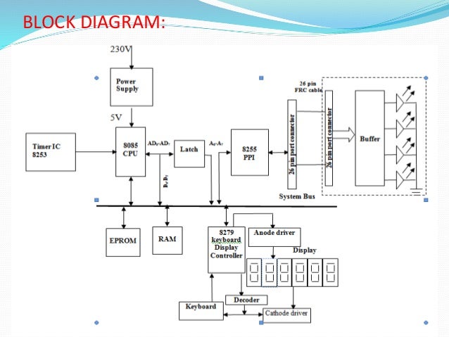
Traffic Light Control System Using Microcontroller

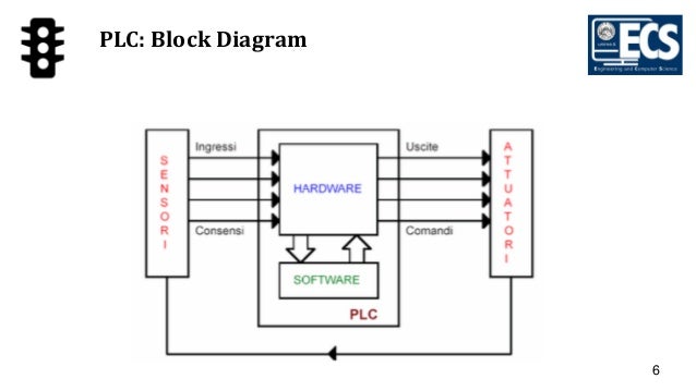
Functional Block Diagram Of A Traffic Light Intersection

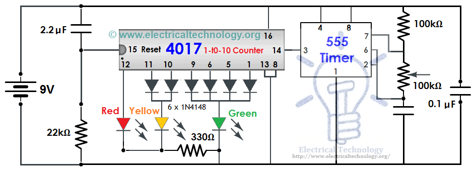
Traffic Light Circuit Diagram Using 555 Timer Ic
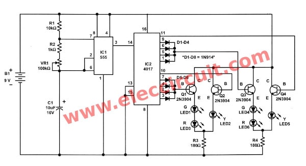
In the above circuit diagram of traffic light controllera seven segment display is used as a counter display and three leds are used for the purpose of traffic light control.
Schematic diagram of traffic light control system. 15 problem statement the monitoring and control of city traffic light is becoming a major problem in many countries. Red green cross traffic now moves. An 8051 microcontroller is the brain of this whole project and is used to initiate the traffic signal at the intersections on road. Red red both lights are red for about one second.
In normal traffic system you have to glow the leds on time basis. The timer here generates pulses of time period 100ms approximately. 1uf 10uf and 22mf capacitors. There are quite a few components which we will be using to make our traffic light control system.
So the on time is 50ms and off time is 50ms. This time duration can be changed by changing the capacitor value. Density based traffic light control system circuit design. Electronic circuit design electronic engineering electrical engineering power supply circuit circuit diagram dc circuit voltage regulator high voltage arduino this is an unique water level indicator circuit which use 7 segment led display to show the current water level in the water tank.
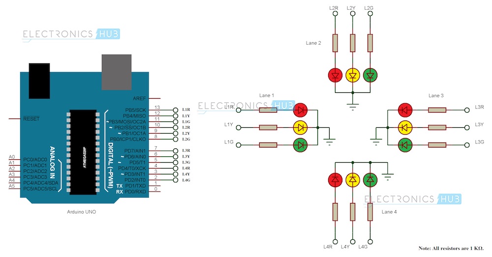
If the traffic density is high on any particular path then glows green led of that particular path and glows the red leds for remaining paths. Programmed a ladder logic diagram to control the traffic light. 9v battery input battery 100k 22k and 330 ohm resistors. The circuit diagram for arduino traffic light controller project is given below.
Flow based traffic light controller system circuit diagram of traffic light using 8051 micro controller this is a sample of traffic signal controller is done by using infrared sensors ir and main part is intel micro controller light emitting diode led with the help of all this component we will make the traffic light controller based on flow of traffic. Connect the leds in the order as red green and yellow in the breadboard. Block diagram of the circuit designed by proteus software. Instead of traffic lights you can use leds red green yellow.
This is the basic sequence for a traffic light without turn signals or features such as an advanced green etc. 555 timer ic as a pulse generator 4017 ic counter main ic of the circuit. Circuit diagram and explanation. To a junction of 4 mono directional roads in the form of as.
One light cross light comments green red traffic moving on one street yellow red traffic on cross street must wait for this light to turn red. Following is the list of the components. Its pretty simple and can be easily built on bread board as explained in below steps. Combine the software part and the hardware part to simulate a traffic light system.

Block Diagram Of The Adaptive Traffic Light Control System

Density Based Traffic Signal System Using Microcontroller

Traffic Light Control System Using Microcontroller

Simple Four Way Traffic Light Circuit
A Traffic Light Control System Using Programmable Logic
Traffic Light Controller Circuit Using Cd4027 Ne555
Part 1 Traffic Light Control Using 8085
Automatic Traffic Light Using Pic16f877a Microcontroller

4 Way Traffic Light Control System Circuit Diagram Using

Figure 2 From Adaptive Traffic Light Control System
Traffic Light Control Electronic Project Using 4017 555 Timer

Circuit Diagram For Density Based Traffic Light Control

Traffic Light Controller Electronics Project
Arduino Traffic Light Controller

Traffic Light Electronic Projects And Circuit Made Easy

Traffic Light Circuit Using Ic 555

4 Way Traffic Lights Diagram In 2019 Traffic Light
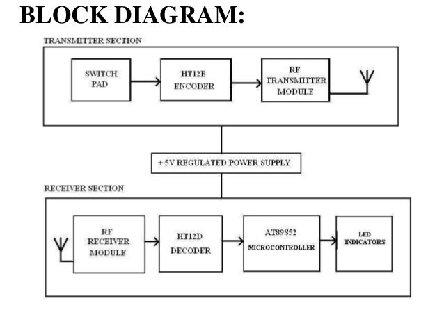
Traffic Light Control Using Rf Tech
