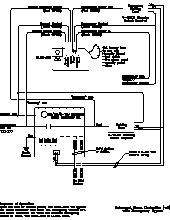
Wattstopper Wiring Diagram

Wattstopper Wiring Diagrams Wiring Schematic Diagram

Lmrc 210 Series Digital On Off 0 10 Volt Dimming Room

Watt Stopper Wiring Diagram Wiring Schematic Diagram

The elcu 200 emergency lighting control unit allows lighting control devices for.
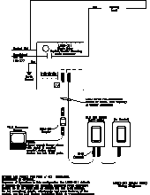
Wattstopper wiring diagram. Connect the neutral for the emergency. There are no obligations. Load as shown in the wiring diagram. The 2 ground wires green and green yellow must be fastened to ground for the sensor to work properly.
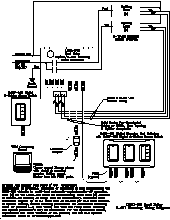
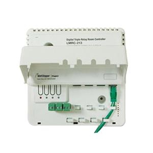
Wattstopper lm mstp wire or equivalent rated lmrc digital onoff volt dimming room controller with 2 relays and 2 the foundation of a wattstopper digital lighting. Dt 355 dual technology line voltage ceiling sensor advanced control logic based on risc micro. The radiant collection is a step up from the standard with simple classic options in wiring devices home automation controls and screwless wall plates that complement todays homes. Lmrc 210 series digital room controllers include one two or three relays to switch a total of 20 amps a high efficiency switching power supply and one 0 10 volt output per relay for control of dimmable loads including electronic ballasts.
4 square 225 deep. 360 dual technology line voltage occupancy sensor with light level feature. Cu wire onlyattach the sensor to the wall box by inserting screws into the two wide holes on the top and bottom of the attached. Lmrc lmrc digital v2.
Dt 355 accessories pdf manual download. Match them up. View and download wattstopper dt 355 installation instructions manual online. Wiring diagram that is appropriate to the pw model and.
Wattstoppers elcu 200 emergency lighting control unit is a self contained device that allows any standard lighting control device to control emergency lighting in conjunction with normal lighting in any area within a building. Dt 300 dual technology ceiling sensor project locationtype advanced control logic based on risc microcon. Radiant screwless wall plate not included. Dt 355 wiring diagram dip switch settings ceiling mounting product controls.
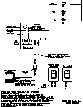
Sample connection diagram with dimming switches and scene control. Wattstopper warranties its products to be free of defects in materials and workmanship for a period of five 5 years. Wattstoppers low profile dt 355 dual technology.
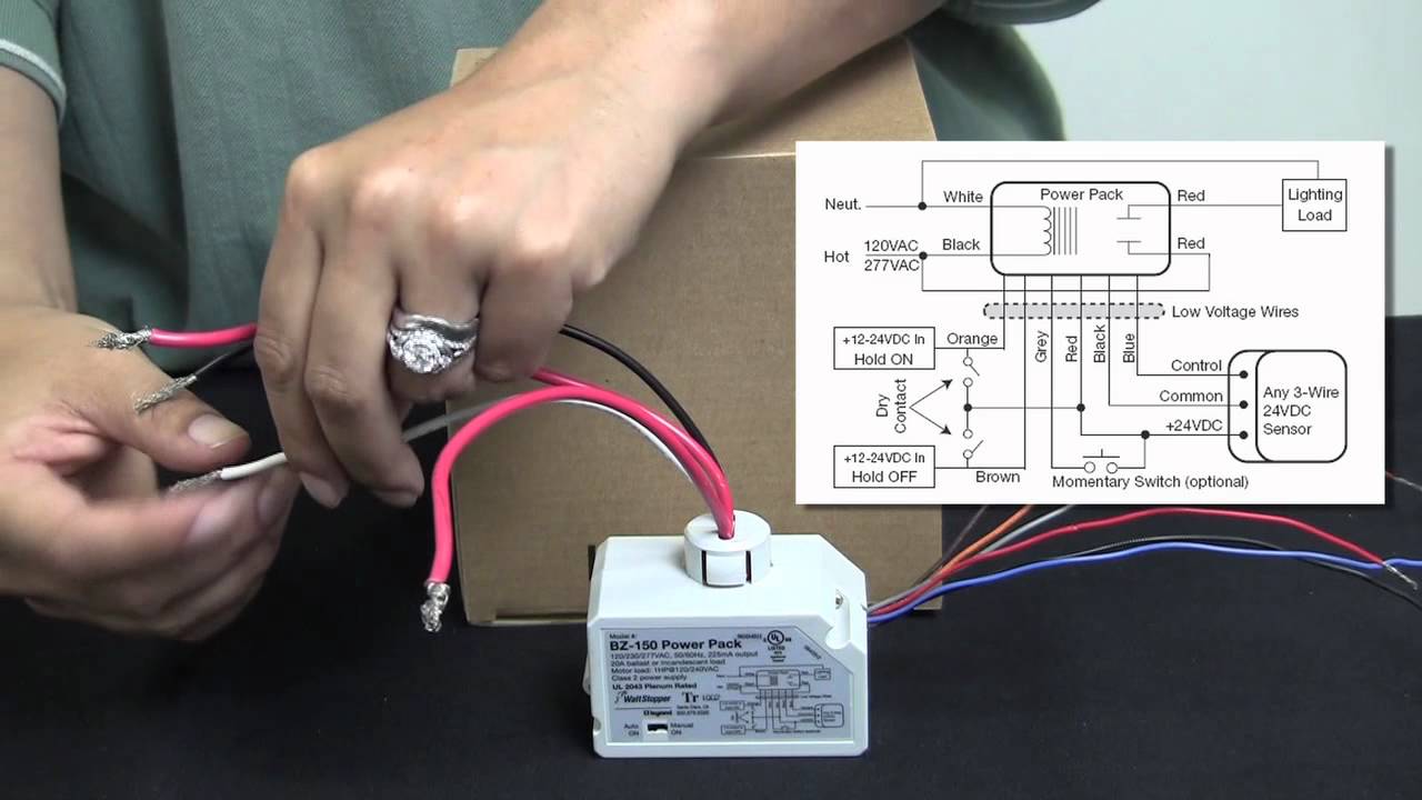
Wattstopper How To Wiring A Bz 150 Universal Voltage Power Pack
Lmrc 210 Series Digital On Off 0 10 Volt Dimming Room
Lmrc 210 Series Digital On Off 0 10 Volt Dimming Room

Watt Stopper Wiring Diagram Wiring Schematic Diagram

Red Wire On Light Switch Top Watt Stopper Power Pack Wiring
Lmrc 210 Series Digital On Off 0 10 Volt Dimming Room

Wattstopper How To Wire A Dt 305 Dual Technology Ceiling Sensor
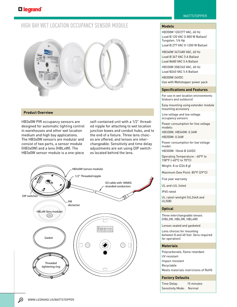
High Bay Wet Location Occupancy Sensor Module

Wattstopper Pw 100 W Wall Switch Occupancy Sensor White Passive Infrared
Wattstopper Lmrc 211 Box Mount On Off 1 Relay Digital Dimming Room Controller 120 277 Volt Ac 800 Milli Amp White

Wattstopper B277e P Power Pack 277v 20 Amps
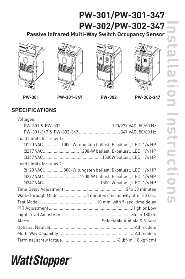
Pw 301 And Pw 302 Installation Instructions

Wattstopper Wiring Diagrams Wiring Schematic Diagram
Lmrc 210 Series Digital On Off 0 10 Volt Dimming Room

Room Controller Installation Part 2
Fm105 Microwave Sensor User Manual Ii Fm 105 08745r1 Indd

Wrg 8765 Wattstopper Wiring Diagram
Wattstopper Lmrc 211 Wiring Diagram
