Honeywell 2 Port Zone Valve Wiring Diagram

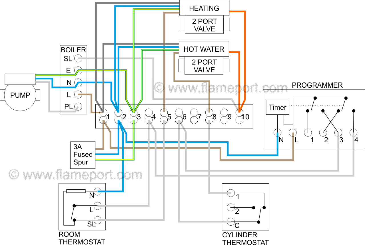
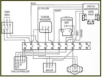
Greenyellow is earth blue is neutral brown is live or line to the motor grey and orange are connected to the end switch and form part of a separate circuit.
Honeywell 2 port zone valve wiring diagram. Wiring diagram shows connections to a programmer each numbered lettered or coloured wire is connected to the with separate control of heating and hot water. Honeywell v4043h installation instructions. The wiring diagrams and installation instructions in this publication are provided for guidance purposes when installing recognised standard systems only. Honeywell 28mm zone valve operation v4043h1106 the honeywell v4043h1106 28mm 2 port zone valve has 6 wires.
A wiring diagram is a streamlined conventional pictorial representation of an electrical circuit. Assortment of honeywell zone valve v8043f1036 wiring diagram. It shows the components of the circuit as streamlined shapes as well as the power as well as signal connections between the tools. Feel pipe approximately 12 from valve port it should get hot.
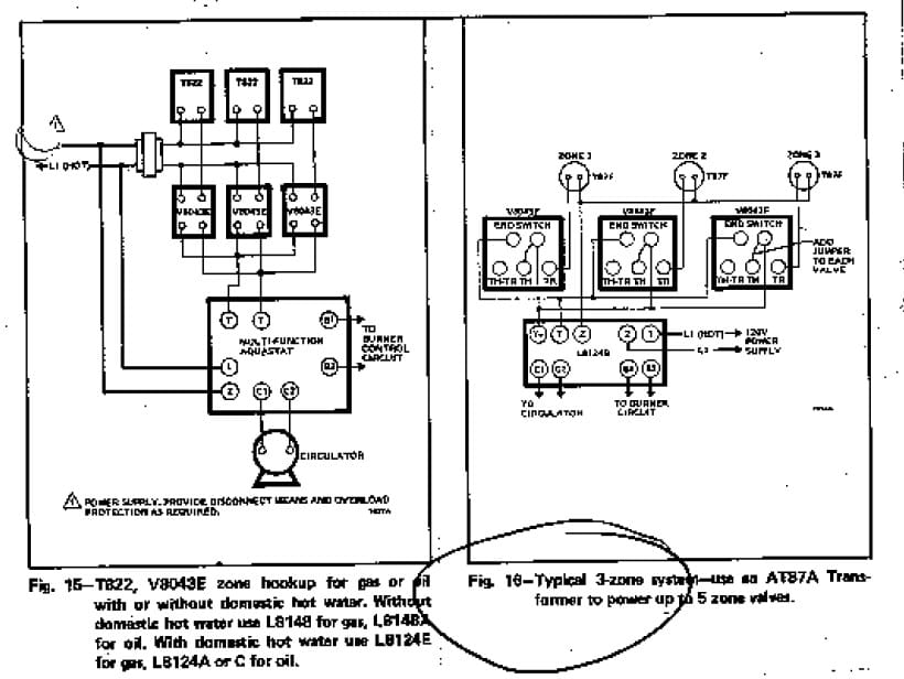
If not the structure wont function as it ought to be. Collection of honeywell gas valve wiring diagram. Honeywell zone valve wiring diagram honeywell 2 port motorised valve wiring diagram honeywell 2 port valve wiring diagram honeywell 2 port zone valve wiring diagram every electric structure is composed of various different parts. Five of these wires are the same as 22mm 2 port valve.
It shows the parts of the circuit as streamlined forms as well as the power as well as signal links in between the gadgets. Each part should be placed and linked to different parts in specific way. More flair zone valve wiring instructions diagrams. Notes to the table above.
The honeywell 5 2 day programmable thermostat rth2300b1012 thermostat cannot be used if your old thermostat had and used any two of the following wires. Faq wiring diagram s plan pump overrun st9420 and dt92e faq wiring diagram s plan plus pump overrun st9420 and dt92e faq wiring diagram combination boiler st9120 t4 additional wiring diagrams lyric t6 additional wiring diagrams v4043 zone valve s plan operation heating controls wiring guide issue 17. R rc rh 4 and v5.


