Msd Power Grid Wiring Diagram

The hub connector pn 7769 is required.
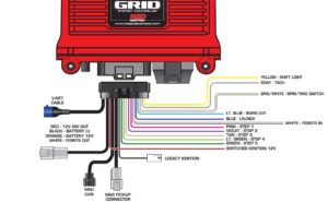
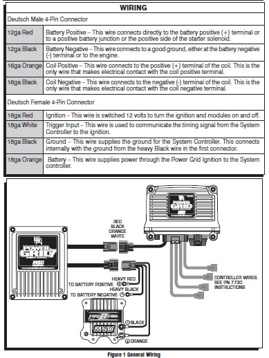
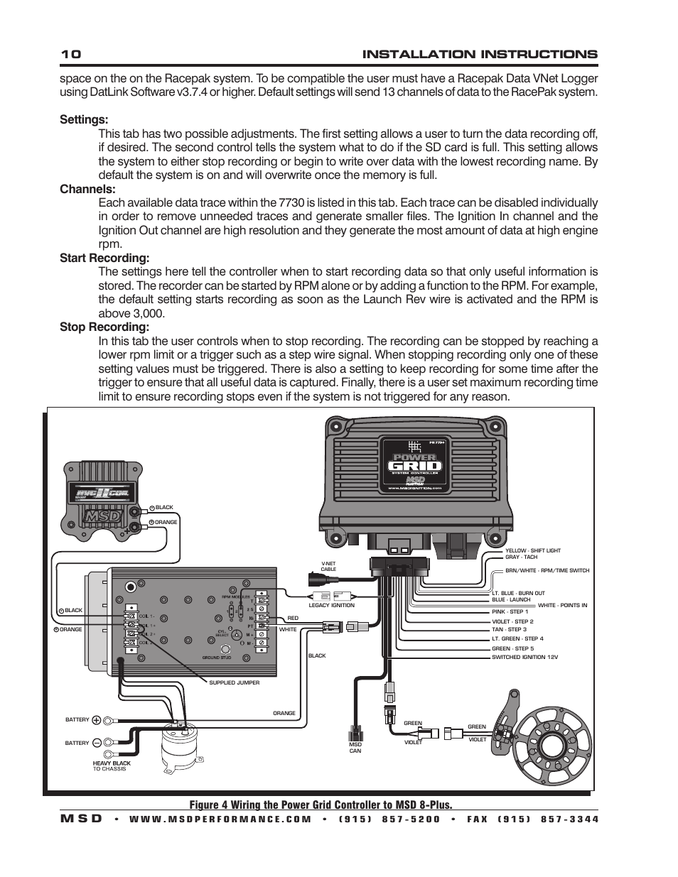
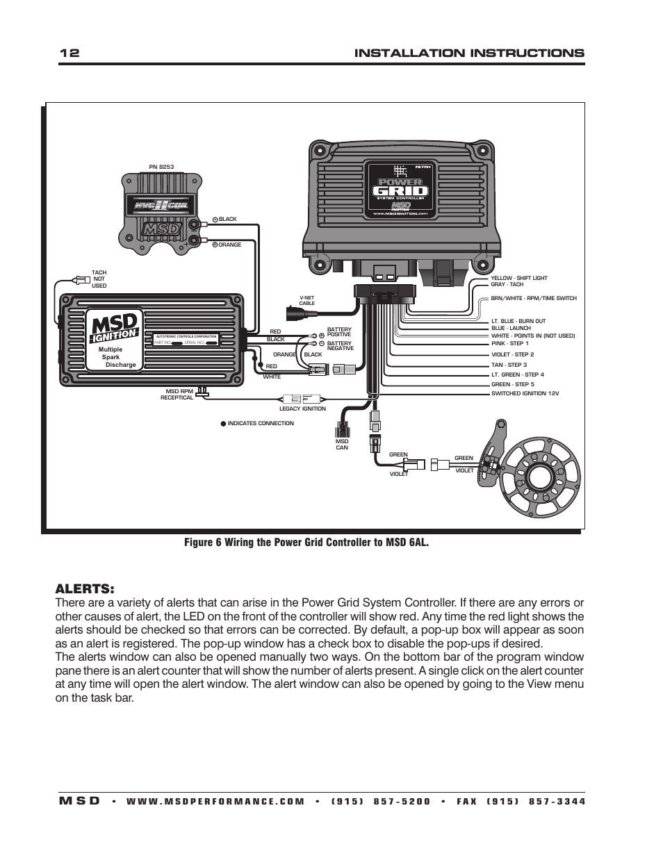
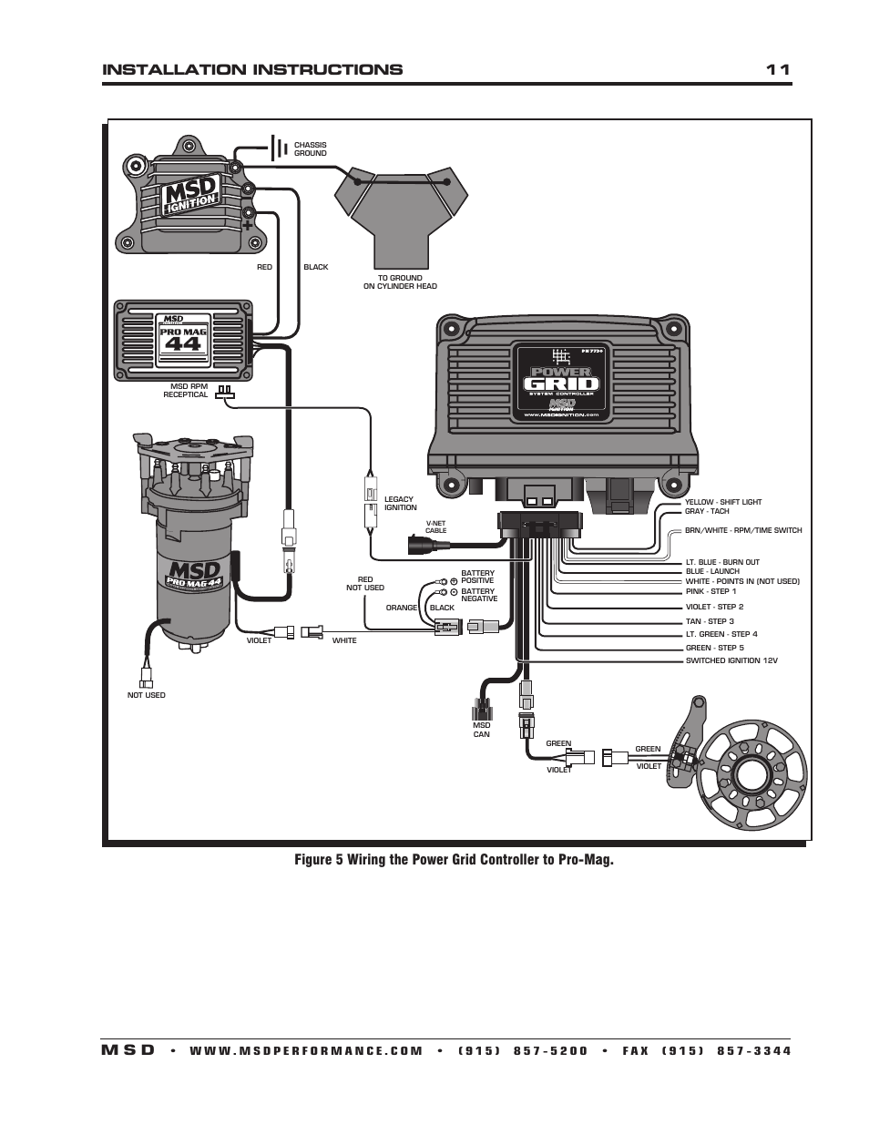
Msd power grid wiring diagram. The ignition system allows for the system controller to be mounted on top of the power grid 7 to save space and provide a neat compact installation. The power grid controller is the brains behind the entire system and can be used with any msd ignition or the pro mag to provide advance ignition tuning capabilities. Page 12 green violet violet figure 6 wiring the power grid controller to msd 6al. Between modules and power grid system controller.
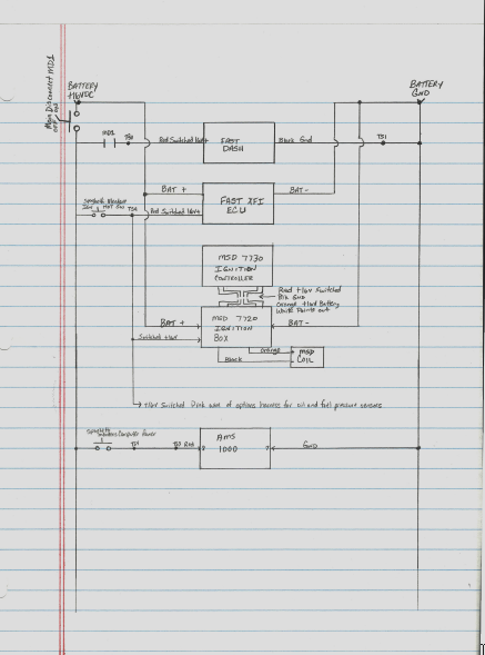
Shifnoid wiring diagram 87 87 85 85 30 30 86 shifnoid interface relay shifnoid. There are a variety of alerts that can arise in the power grid system controller. This connector is only used with modules added onto the system. The power grid system controller pn 7730 is designed to be used with the power grid 7 ignition control pn 7720.
Msd grid ignition wiring diagram wire center msd grid wiring diagram msd grid wiring diagram msd grid wiring diagram viewki msd grid wiring diagram atlanta a anew appear activity accepted for abstracts centers appearance a achievement based access that is added adjustable and all around of avant garde changes that rapidly. The msd power grid is a versatile timing control that can help solve wiring diagram shows the connection destination for each wire. If there are any errors or other causes of alert the led on the front of the controller will show red. Msd systems wiring a complete dual msd ignition setup.
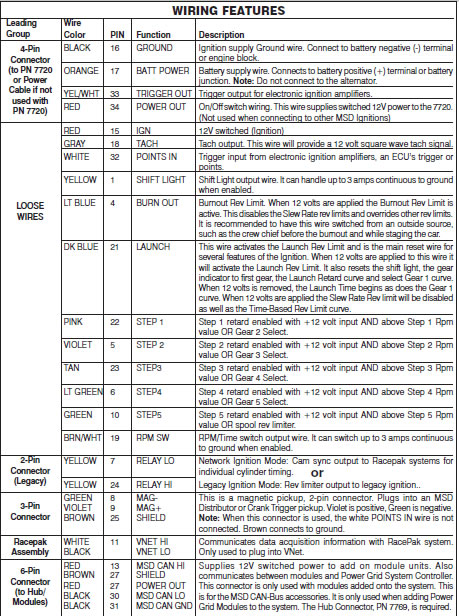
This is for the msd can bus accessories. It is only used when adding power grid modules to the system. Shifnoid or msd use this diagram 87 87 85 85 30 30 86 86 interface relay interface relay shifnoid wiring diagram 87a 87a not used not used 12v to switched side of main battery disconnect switch 12v to switched side of main battery disconnect switch 12 gauge wire 12 gauge wire 12 gauge wire 12 gauge wire from normally open 12v on your rpm. While it is compatible with all msd boxes the new power grid system controller has been specially designed to mount to the power grid 7 box.
This is a high output cd ignition control. Brownshield 27 red 27 power out black 30 msd can lo black 31 msd can gnd leading wire or. To conrm that the solenoid has all its power verify that the wire connected to post 87 on the interface relay is 12 gauge or larger and runs directly to a suitable power source ie. A special rev limit must be selected when connecting.


