Vdo Fuel Gauge Wiring Diagram

Use is restricted to 12 volt negative ground electrical systems.
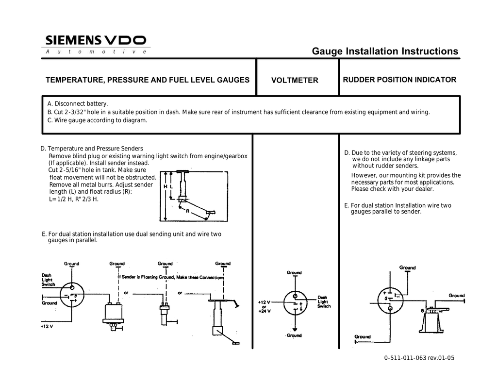
Vdo fuel gauge wiring diagram. These instructions are for vdo gauges and accessories only. Locate this demension. Parts of the fuel level sender unit to be ad fuel level sender installation. Ment refer to table 1 and diagram c.
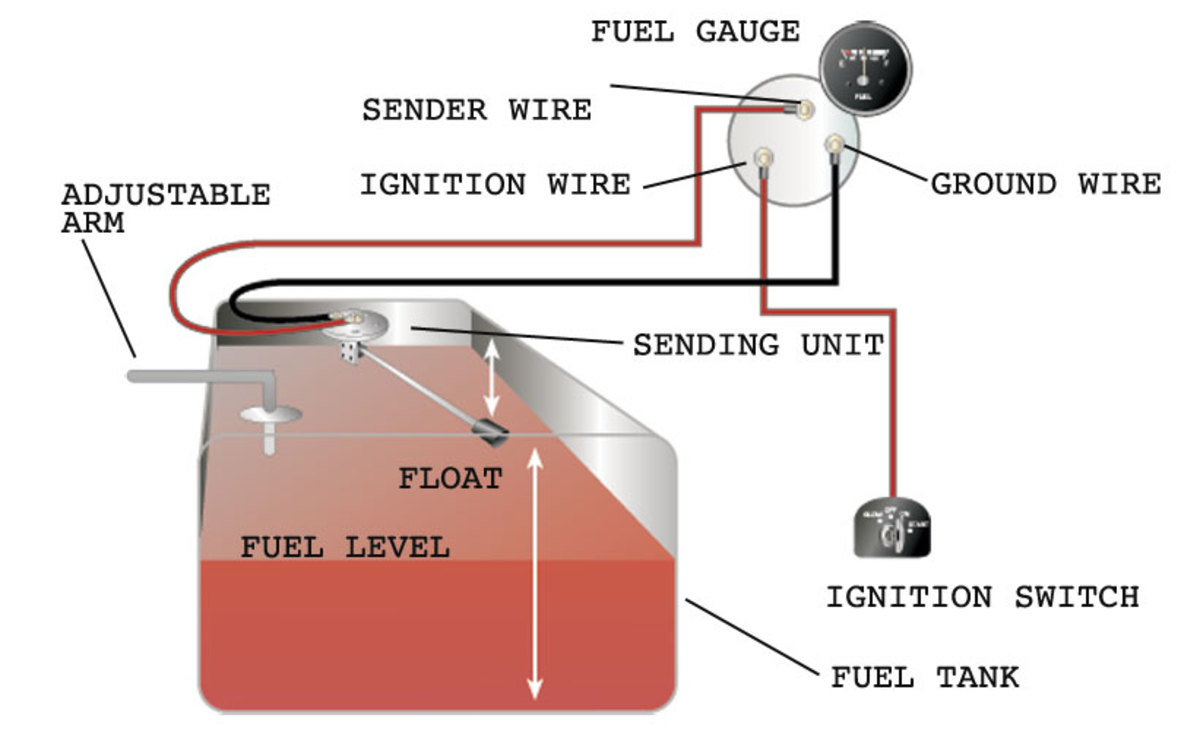
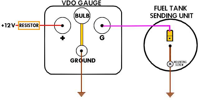
Please note that if you have a problem opening the pdf files just by clicking on the link please right click your mouse button over the file name and select save target as to your desktop. Measure the depth of your fuel tank. Measure the tank depth of your fuel tank. Next connect a wire from the float on the fuel tank to the negative terminal of the fuel gauge.
Light bulb if supplied is 12. Always disconnect battery ground before making any electrical. Always disconnect battery ground before making any electrical connections. Etb fuel level sensor float arm type notes on fitting.
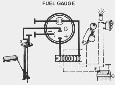
This fuel sender is designed to mount on all fuel tanks with a. Gauge illumination wiring and wiring of senders to each gauge. Vdo temperature sensors vdo pressure sensors vdo fuel level sensors vdo speed. Fuel gauge wiring diagram download wire center.
With the tank empty use the calibration screw to move the pointer to e when the pointer rests on e with the tank empty the gauge and sender are calibrated and ready for use and the gauge can be wiring the fuel gauge. Procedures for installing vdo viewline instruments. Viewline 52 mm temperature gauge pressure gauge rudder angel gauge. Marine fuel gauge wiring diagram download collections of wiring diagrams for vdo gauges valid marine fuel gauge wiring.
Fuel gauge fresh water gauge for level type sensor. Refer to the vdo catalog for matching fuel gauges. Obtain 12 volt power from the fuse box using a standard wire and connect it to the positive terminal of the fuel gauge. After wiring gaugesender calibrate them diagram e.
Click here for auto meter classic instruments defi or isspro instructions. According to the electrical wiring diagram. 0 515 012 185 instrument kit with mech speedocpdf. Wire a fuel gauge by first disconnecting the old dysfunctional unit to replace it with a new one.
The fuel gauge should now show the correct fuel level in. Run wires from the adjustable fuel gauge. If operating the instrument on power supply units note that the. 0 515 012 123 electric gaugesp65.
52mm water oil temperature oil pressure fuel gauge voltmeter and capacitive advance clock wiring diagram. Sensors for vdo gauges. Check the wiring diagram that comes with the kit and mark the back of the new fuel gauge with symbols for each post. Fuel gauge wiring diagram additionally boat fuel gauge wiring.
Do not deviate from assembly or wiring instructions. Fuel gauge sending unit wiring diagram ford truck diagrams fancy. Pressure andor fuel gauge are contained herein.
